proyectos:jardin_delicias:tecnologicos:microprocesadores-esp8266
Tabla de Contenidos
Microprocesadores ESP8266
ESP8266: son microprocesadores (piense Arduino) con WiFi integrado. Son más pequeños que una moneda y consumen muy poca energía. Se le pega un sensor a un ESP para que éste lee los datos y los transmita vía WiFi a un servidor
Conexión y Programación del ESP8266
Los pines del ESP8266 están mapeados así. 
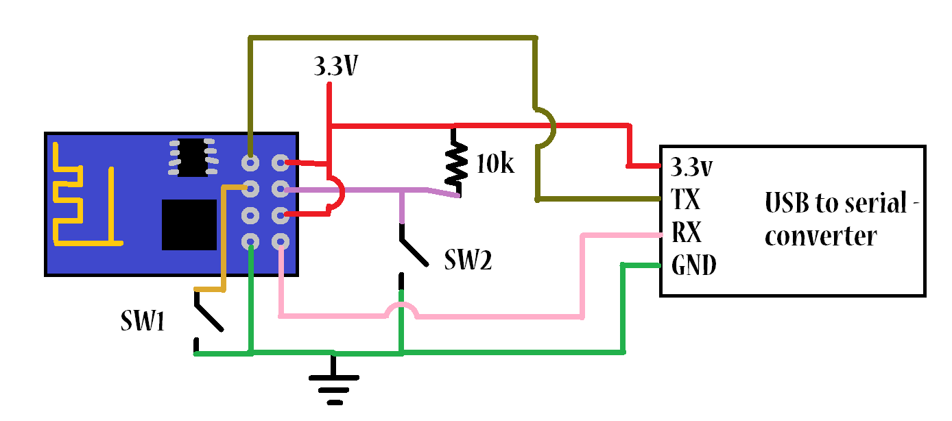
Se usa un arduino uno para tomar de el los 3v3 voltios y así alimentar el ESP. Para programarlo por medio de un integrado FTDI se sigue el siguiente esquema
Montaje para ESP-1
Montaje para ESP-12

Para programar el ESP es necesario poner el gpio0 al tierra, solo para programarlo. Esto lo dice acá http://i.imgur.com/R6Afzju.png y acá http://iot-playground.com/2-uncategorised/35-esp8266-firmware-update
obtenido de http://blog.theinventorhouse.org/mi-primer-acercamiento-al-modulo-wifi-esp8266/
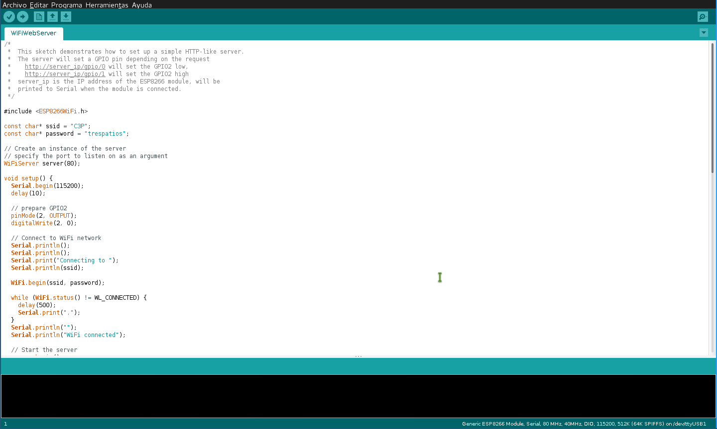
Todo se hace a través del IDE de Arduino después de configurarlo como se explica arriba 1)
Configuración del IDE
Usar IDE de Arduino para programar ESP8266
Fuente → https://github.com/esp8266/Arduino#arduino-core-for-esp8266-wifi-chip
This project brings support for ESP8266 chip to the Arduino environment. It lets you write sketches using familiar Arduino functions and libraries, and run them directly on ESP8266, no external microcontroller required.
ESP8266 Arduino core comes with libraries to communicate over WiFi using TCP and UDP, set up HTTP, mDNS, SSDP, and DNS servers, do OTA updates, use a file system in flash memory, work with SD cards, servos, SPI and I2C peripherals. Installing with Boards Manager
Starting with 1.6.4, Arduino allows installation of third-party platform packages using Boards Manager. We have packages available for Windows, Mac OS, and Linux (32 and 64 bit).
- Install Arduino 1.6.5 from the Arduino website.
- Start Arduino and open Preferences window.
- Enter http://arduino.esp8266.com/stable/package_esp8266com_index.json into Additional Board Manager URLs field. You can add multiple URLs, separating them with commas.
- Open Boards Manager from Tools > Board menu and install esp8266 platform (and don't forget to select your ESP8266 board from Tools > Board menu after installation).
Programación con esptool
“esptool is a cute Python utility to communicate with the ROM bootloader in Espressif ESP8266. It is intended to be a simple, platform independent, open source replacement for XTCOM.”2)
Repositorio de la herramienta de python esptool → https://github.com/themadinventor/esptool
Guía para usar esptool para programar NodeMCU → http://www.whatimade.today/flashing-the-nodemcu-firmware-on-the-esp8266-linux-guide/
Existen otros firmwares como dice en este wiki http://www.electrodragon.com/w/Category:ESP8266_firmware
ESPressif AT firmware
espressif es la empresa que creó el integrado, la versión que se prueba es at_v0.20_on_SDKv0.9.3
https://github.com/espressif/esp8266_at/tree/master/bin
Se programa con esptool en las siguiente direcciones de la flash
Please download these bins to the specified address.

Bin                           Address
boot_v1.1.bin---------------->0x00000
user1.bin-------------------->0x01000    ---> you can use the newest version or a specific version.
esp_init_data_default.bin---->0x7C000
blank.bin-------------------->0x7E000
esptool.py --port /dev/ttyUSB0 write_flash 0x7E000 ATFirmware/at_v0.20_on_SDKv0.9.3/bin/blank.bin 0x00000 ATFirmware/at_v0.20_on_SDKv0.9.3/bin/boot_v1.1.bin 0x01000 ATFirmware/at_v0.20_on_SDKv0.9.3/bin/user1.bin
Connecting...
Erasing flash...
Writing at 0x0007ec00... (100 %)
Erasing flash...
Writing at 0x00000400... (100 %)
Erasing flash...
Writing at 0x00036c00... (100 %)

Leaving...
NodeMCU firmware
Este firmware convierte el ESP en un intérprete de comando lua. Posee un API para acceder a las características del microcontrolador:
API NodeMCU http://www.nodemcu.com/docs/
- node module
- file module
- wifi module
- wifi.sta module
- wifi.ap module
- timer module
- GPIO module
- PWM module
- net module
- net.server module
- net.socket module
- i2c module
- adc module
- uart module
- onewire module
- bit module
- spi module
- mqtt module
- mqtt client module
permite alojar scripts dentro de un sistema de archivos basado en (SPI Flash File System)https://github.com/pellepl/spiffs, los archivos se suben a través de una interfaz serial. Son scripts .lua. ESPlorer es un Integrated Development Environment (IDE) for ESP8266 developers. https://github.com/4refr0nt/ESPlorer

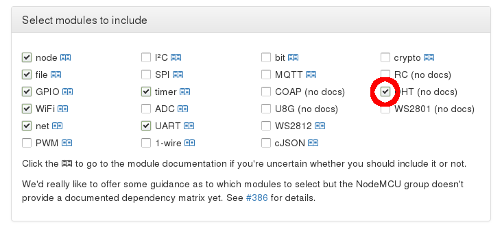
Se crea un firmware a la medida con → http://frightanic.com/nodemcu-custom-build/index.php
Y se baja con
esptool.py --port /dev/ttyUSB0 write_flash 0x00000 /home/brolin/Proyectos/MDE15/ESP8266/CustomBuild/nodemcu-master-14-modules-2015-08-23-02-49-59-integer.bin
El nodeMCU ejecuta una vez arranca, el archivo llamado init.lua y desde este se puede llamar otros scripts. Se prueba una serie de scripts (sacados de acá http://www.esp8266.com/viewtopic.php?p=10852) que cuando arranca el ESP trata de conectarse a la última red wifi establecida, si no lo logra crea un AP con essid ConfigureMe-XX para settear la red a la cual conectarse. Después de estar conectado ejecuta el script task.lua
Los archivos que se suben son:
init.lua
timeout = 30 -- seconds to wait for connect before going to AP mode

statuses = {[0]="Idle",
            [1]="Connecting",
            [2]="Wrong password",
            [3]="No AP found",
            [4]="Connect fail",
            [5]="Got IP",
            [255]="Not in STATION mode"}

checkCount = 0
function checkStatus()
  checkCount = checkCount + 1
  local s=wifi.sta.status()
  print("Status = " .. s .. " (" .. statuses[s] .. ")")
  if(s==5) then -- successful connect
    launchApp()
    return
  elseif(s==2 or s==3 or s==4) then -- failed
    startServer()
    return
  end
  if(checkCount >= timeout) then
    startServer()
    return
  end
end

function launchApp()
  cleanup()
  print("I'm connected to my last network. Launching my real task.")
  local task = 'task.lua'
  local f=file.open(task, 'r')
  if(f == nil) then
    print('Error opening file ' .. task)
    return
  end
  file.close()
  dofile(task)
end

function startServer()
  lastStatus = statuses[wifi.sta.status()]
  cleanup()
  print("network not found, switching to AP mode")
  dofile('configServer.lua')
end

function cleanup()
  -- stop our alarm
  tmr.stop(0)
  -- nil out all global vars we used
  timeout = nil
  statuses = nil
  checkCount = nil
  -- nil out any functions we defined
  checkStatus = nil
  launchApp = nil
  startServer = nil
  cleanup = nil
  -- take out the trash
  collectgarbage()
  -- pause a few seconds to allow garbage to collect and free up heap
  tmr.delay(5000)
end

-- make sure we are trying to connect as clients
wifi.setmode(wifi.STATION)
wifi.sta.autoconnect(1)

-- every second, check our status
tmr.alarm(0, 1000, 1, checkStatus)
configServer.lua
dofile("configServerInit.lua")

apRefresh = 15 -- how many seconds between when we scan for updated AP info for the user
currentAPs = {}

newssid = ""

function listAPs_callback(t)
  if(t==nil) then
    return
  end
  currentAPs = t
end

function listAPs()
  wifi.sta.getap(listAPs_callback)
end

function sendPage(conn)
  conn:send('HTTP/1.1 200 OK\n\n')
  conn:send('<!DOCTYPE HTML>\n<html>\n<head><meta content="text/html; charset=utf-8">\n<title>Device Configuration</title></head>\n<body>\n<form action="/" method="POST">\n')

  if(lastStatus ~= nil) then
    conn:send('<br/>Previous connection status: ' .. lastStatus ..'\n')
  end

  if(newssid ~= "") then
    conn:send('<br/>Upon reboot, unit will attempt to connect to SSID "' .. newssid ..'".\n')
  end

  conn:send('<br/><br/>\n\n<table>\n<tr><th>Choose SSID to connect to:</th></tr>\n')

  for ap,v in pairs(currentAPs) do
    conn:send('<tr><td><input type="button" onClick=\'document.getElementById("ssid").value = "' .. ap .. '"\' value="' .. ap .. '"/></td></tr>\n')
  end

  conn:send('</table>\n\nSSID: <input type="text" id="ssid" name="ssid" value=""><br/>\nPassword: <input type="text" name="passwd" value=""><br/>\n\n')
  conn:send('<input type="submit" value="Submit"/>\n<input type="button" onClick="window.location.reload()" value="Refresh"/>\n<br/>If you\'re happy with this...\n<input type="submit" name="reboot" value="Reboot!"/>\n')
  conn:send('</form>\n</body></html>')

end

function url_decode(str)
  local s = string.gsub (str, "+", " ")
  s = string.gsub (s, "%%(%x%x)",
      function(h) return string.char(tonumber(h,16)) end)
  s = string.gsub (s, "\r\n", "\n")
  return s
end

function incoming_connection(conn, payload)
  if (string.find(payload, "GET /favicon.ico HTTP/1.1") ~= nil) then
    print("GET favicon request")
  elseif (string.find(payload, "GET / HTTP/1.1") ~= nil) then
    print("GET received")
    sendPage(conn)
  else
    print("POST received")
    local blank, plStart = string.find(payload, "\r\n\r\n");
    if(plStart == nil) then
      return
    end
    payload = string.sub(payload, plStart+1)
    args={}
    args.passwd=""
    -- parse all POST args into the 'args' table
    for k,v in string.gmatch(payload, "([^=&]*)=([^&]*)") do
      args[k]=url_decode(v)
    end
    if(args.ssid ~= nil and args.ssid ~= "") then
      print("New SSID: " .. args.ssid)
      print("Password: " .. args.passwd)
      newssid = args.ssid
      wifi.sta.config(args.ssid, args.passwd)
    end
    if(args.reboot ~= nil) then
      print("Rebooting")
      conn:close()
      node.restart()
    end
    conn:send('HTTP/1.1 303 See Other\n')
    conn:send('Location: /\n')
  end
end

-- start a periodic scan for other nearby APs
tmr.alarm(0, apRefresh*1000, 1, listAPs)
listAPs() -- and do it once to start with

-- Now we set up the Web Server
srv=net.createServer(net.TCP)
srv:listen(80,function(sock)
  sock:on("receive", incoming_connection)
  sock:on("sent", function(sock)
    sock:close()
  end)
end)
configServerinit.lua
apNamePrefix = "ConfigureMe" -- your AP will be named this plus "-XX-YY", where XX and YY are the last two bytes of this unit's MAC address

apNetConfig = {ip      = "192.168.4.1", -- NodeMCU seems to be hard-coded to hand out IPs in the 192.168.4.x range, so let's make sure we're there, too
               netmask = "255.255.255.0",
               gateway = "192.168.4.1"}

-- Set up our Access Point with the proper name and settings
local apName = apNamePrefix .. "-" .. string.sub(wifi.ap.getmac(),13)
print("Starting up AP with SSID: " .. apName);
wifi.setmode(wifi.STATIONAP)
local apSsidConfig = {}
apSsidConfig.ssid = apName
wifi.ap.config(apSsidConfig)
wifi.ap.setip(apNetConfig)
Conexión ESP-12

Explicación detallada del chip http://hackaday.com/2015/03/18/how-to-directly-program-an-inexpensive-esp8266-wifi-module/
http://www.instructables.com/id/Getting-Started-with-the-ESP8266-ESP-12/step2/Add-power-supply/
Las boards que se compraron tienen la posibilidad de agregarles directamente el regulador de voltaje de 3v3 entonces al pin VCC no le llega corriente si no tiene este pegado en la board. Los reguladores que compramos para protoboard son más grandes que los que deben ir ahí. ( )
)
Así quedó montado en protoboard nuestro programador:


Sensor DHT-11 con esp-12
La conexión del circuito es muy sencilla como se ve en la siguiente imagen (tomada de http://domoticx.com/arduino-modules-temperatuur-en-luchtvochtigheid-sensor-module-dht11/)

Si genera la imagen del firmware desde http://frightanic.com/nodemcu-custom-build/index.php asegúrese de seleccionar el módulo dht
Como lo hicimos antes, “flashee” el firmware al ESP con esptool
esptool.py --port /dev/ttyUSB0 write_flash 0x00000 /home/brolin/Proyectos/MDE15/ESP8266/CustomBuild/nodemcu-master-15-modules-2015-09-25-22-25-34-integer.bin
El programa que lee los datos del sensor DHT-11 es el siguiente (adaptando este http://www.kutukupret.com/2015/09/24/esp8266-nodemcu-dht22-and-thingspeak-api/)
PIN = 7                --  data pin
humi=0
temp=0
id=0

--load DHT module and read sensor
function ReadDHT()
    id = id + 1
    dht=require("dht")
    -- dht.read(PIN)
    status,temp,humi,temp_decimial,humi_decimial = dht.read(PIN)
        if( status == dht.OK ) then
          -- Integer firmware using this example
            print(
                string.format(
                    "\r\nDHT Temperature:%d.%03d\r\nHumidity:%d.%03d\r\n",
                    temp,
                    temp_decimial,
                    humi,
                    humi_decimial
                )
            )
            -- Float firmware using this example
            print("Humidity:    "..humi.."%")
            print("Temperature: "..temp.."C")
        elseif( status == dht.ERROR_CHECKSUM ) then
            print( "DHT Checksum error." );
        elseif( status == dht.ERROR_TIMEOUT ) then
            print( "DHT Time out." );
        end
    -- release module
    dht=nil
    package.loaded["dht"]=nil
end
-- send to https://api.thingspeak.com
function sendTS(humi,temp)
local sensorId = "\"c3p\""
local json = '{"sensorId":'..sensorId..',"temperature_value":'..temp..',"humidity_value":'..humi..',"id":'..id..'}'
conn = nil
conn = net.createConnection(net.TCP, 0)
conn:on("receive", function(conn, payload)success = true print(payload)end)
conn:on("connection",
   function(conn, payload)
   print("Connected")
   conn:send("POST /sensorData HTTP/1.0\r\n"

            -- Add the Application key to the header we send in the post request.
            .."Host: eljardindelasdelicias.unloquer.org\r\n"
            .."User-Agent: Mozilla/4.0 (compatible; esp8266 Lua; Windows NT 5.1)\r\n"

            -- Add the length of the string we send.
            .."Content-Length: "..string.len(json).."\r\n"
            .."\r\n"

            -- Add the JSON string to the post object.
            ..json)end)

conn:on("disconnection", function(conn, payload) print('Disconnected') end)
conn:connect(1337,'104.131.1.214')
end
ReadDHT()
sendTS(humi,temp)
tmr.alarm(1,600000,1,function()ReadDHT()sendTS(humi,temp)end)
Mapeo de pines entre ESP-12 y node MCU
En la primera línea del código se establece el pin a través del cual voy a leer los datos del sensor. El mapeo de pines de nodeMCU corresponde a los pines físicos de la tarjeta ESP-8266 según la siguiente tabla:
| IO index | ESP8266 pin |
|---|---|
| 0 [*] | GPIO16 |
| 1 | GPIO5 |
| 2 | GPIO4 |
| 3 | GPIO0 |
| 4 | GPIO2 |
| 5 | GPIO14 (SPI CLK) |
| 6 | GPIO12 (SPI MISO) |
| 7 | GPIO13 (SPI MOSI) |
| 8 | GPIO15 (SPI CS) |
| 9 | GPIO3 (UART RX) |
| 10 | GPIO1 (UART TX) |
| 11 | GPIO9 |
| 12 | GPIO10 |
Optimizar el consumo de potencia
Leer e implementar
https://www.hackster.io/fablabeu/esp8266-thing-by-sparkfun
https://github.com/nodemcu/nodemcu-firmware/wiki/nodemcu_api_en#nodedsleep
El ESP8266 ESP-12 solo tiene un pin ADC expuesto y el ESP-01 no tiene, ¿cómo leer sensores análogos entonces?
Agregando un ADC por funcione por i2c → http://www.hobbytronics.co.uk/arduino-adc-i2c-slave
De este producto en tindie https://www.tindie.com/products/AllAboutEE/esp8266-analog-inputs-expander/ que usa un ADC MAX11609EEE, en este repositorio está todo el código y el diseño de hardware https://github.com/AllAboutEE/MAX11609EEE-Breakout-Board
En una versión anterior usaron el chip de microchip MCP3021 https://github.com/AllAboutEE/ESP8266-MCP3021-Library esto solo tiene un canal por chip. También es posible usar el ADC MCP3808 de microchip http://www.microchip.com/wwwproducts/Devices.aspx?product=MCP3008 que tiene la misma funcionalidad del MAX11609EEE.
Hay algunos diseños en github para el MCP3008 como https://github.com/bricogeek/mcp3008_breakout, dado que este integrado no necesita resistencias o capacitores externos para funcionar (VERIFICAR ESTO:!:) es posible también usar una placa genérica SOIC-16 como este http://didacticaselectronicas.com/index.php?page=shop.product_details&flypage=flypage.tpl&product_id=1332&category_id=186&keyword=soic&option=com_virtuemart&Itemid=179
- Acá hay muchos diseños de hardware interesantes para mirar https://github.com/thinkl33t/PCB-Designs
- Driver genérico i2c → https://github.com/zarya/esp8266_i2c_driver
- Explicación detallada de la arquitectura y algunas funcionalidades del ESP8266 → https://nurdspace.nl/ESP8266#Ultra-low_power_technology
Protocolos I2C y SPI
http://www.byteparadigm.com/applications/introduction-to-i2c-and-spi-protocols/
SPI utiliza mínimo 4 líneas
- SLCK → Reloj
- S_SELECT_N → Selector del chip slave N
- MOSI → Master Out Slave In
- MISO → Master In Slave Out
I2C utiliza 2 líneas
- SCL → Reloj
- SDA → Datos
I2c por el mismo bus selecciona el dispostivo al que quiere hablarle enviando su dirección y esperando reconocimiento de la comunicación y los datos si es el caso
Conclusión sobre las diferencias de los dos protocolos “In the world of communication protocols, I²C and SPI are often considered as ‘little’ communication protocols compared to Ethernet, USB, SATA, PCI-Express and others, that present throughput in the x100 megabit per second range if not gigabit per second. Though, one must not forget what each protocol is meant for. Ethernet, USB, SATA are meant for ‘outside the box communications’ and data exchanges between whole systems. When there is a need to implement a communication between integrated circuit such as a microcontroller and a set of relatively slow peripheral, there is no point at using any excessively complex protocols. There, I²C and SPI perfectly fit the bill and have become so popular that it is very likely that any embedded system engineer will use them during his/her career.”3)
Comunicación I2C del ESP8266
Explicar los módulos de lua que permiten esto
Integrado ADS1115
Este integrado tiene 4 canales independientes o puede trabajar en modo diferencial limitando a dos canales diferencial.
Tiene un protocolo específico para configurar y obtener los datos del integrado definido en el datasheet http://www.ti.com/lit/gpn/ads1115
Existe una tabla para definir la address del conversor i2c definida así. Se conecta el pin ADDR PIN a cualquiera de los pines de la siguiente tabla. Se establece la dirección según lo dice en la columna SLAVE ADDRESS
| ADDR PIN | SLAVE ADDRESS |
|---|---|
| Ground | 1001000 |
| VDD | 1001001 |
| SDA | 1001010 |
| SCL | 1001011 |
El integrado ADS1115 tiene 4 registros a los que se acceden a través de I2C. Dentro de un registro principal llamado pointer register se encuentran los “sub-registros”:
- Config Register
- Conversion Register
- Lo_Threshold y Hi_Threshold
… continua, sale de la información en el datasheet.
Conexión ADS1115 con ESP8266
ADS1115 ESP8266
GND → GND
VDD → VCC
SCL → GPIO5
SDA → GPIO4
A0 → Señal Positiva
A1 → Señal Negativa
Se usa un código de arduino basado en EmonLib sacado de http://www.seeedstudio.com/recipe/377-esp8266-iot-energy-monitor.html.
En la página muestran la conexión basada en un kit de desarrollo NodeMCU, el mapeo de pines es el siguiente.
 Está diseñado para funcionar con el ESP-1.
Este código pone a funcionar el conversor A/D en modo diferencial
LA IDEA ES CREAR UNA LIBRERIA EN LUA BASADA EN LA HECHA PARA EL ENTORNO ARDUINO
/*
 *  This sketch sends ads1115 current sensor data via HTTP POST request to thingspeak server.
 *  It needs the following libraries to work (besides the esp8266 standard libraries supplied with the IDE):
 *
 *  - https://github.com/adafruit/Adafruit_ADS1X15
 *
 *  designed to run directly on esp8266-01 module, to where it can be uploaded using this marvelous piece of software:
 *
 *  https://github.com/esp8266/Arduino
 *
 *  2015 Tisham Dhar
 *  licensed under GNU GPL
 */

#include <ESP8266WiFi.h>
#include <Wire.h>
#include <Adafruit_ADS1015.h>


Adafruit_ADS1115 ads;  /* Use this for the 16-bit version */

void setup() {
  Serial.begin(115200);
  delay(10);

  ads.setGain(GAIN_ONE);        // 1x gain   +/- 4.096V  1 bit = 2mV      0.125mV
  ads.begin();
}

void loop() {

  double voltage = ads.readADC_Differential_0_1();
  Serial.print(millis());Serial.print(",");
  Serial.println(voltage);

  //delay(1000);
}


Se exportan los datos en formato CSV y se genera una gráfica usando el lenguaje R.

Donde baja el nivel de la señal coincide con el momento donde se tiene interacción con la planta (tocarla)
Referentes
https://github.com/adafruit/Adafruit-Raspberry-Pi-Python-Code/tree/master/Adafruit_ADS1x15
http://logicware.myshopify.com/products/ads1015-adc-4-channel-12-bit-precision-i2c-and-pga-arduino-and-raspberry-pi-2
https://github.com/adafruit/Adafruit_ADS1X15
Integrado ADS1118
Comunicación SPI del ESP8266
http://d.av.id.au/blog/page/2/
https://github.com/MetalPhreak/ESP8266_SPI_Driver
https://www.youtube.com/watch?v=vG-Dcr0BFBc
ESP8266 + LPD8806 LedStrip
Usando el ide de arduino en modo ESP8266, se compila el ejemplo de la librería LPD8806 incluyendo en el código la librería ESP8266WiFi.h. Se usan los pines GPIO4 como reloj y GPIO5 como datos. Para 16 leds funciona perfectamente alimentada con 3.5V.


Librería para arduino https://github.com/adafruit/LPD8806/blob/master/LPD8806.cpp
New kid in the block http://es.aliexpress.com/wholesale?catId=0&initiative_id=&SearchText=EMW3165
Construcción de sistemas completos
- IoTBox → http://blog.spants.com/
- ESP8266 MQTT battery monitor project → http://dangerousprototypes.com/2015/08/03/esp8266-mqtt-battery-monitor-project/
- Irrigation Controller → http://www.instructables.com/id/ESP8266-Irrigation-Controller/
- Wifi internet relay → http://www.instructables.com/id/WiFi-Internet-Controlled-Relays-using-ESP8266-Quic/
- ESP8266 + RaspberryPi → http://www.instructables.com/id/Connect-an-ESP8266-to-your-RaspberryPi/?ALLSTEPS
Referentes
- GardenBot → http://www.gardenbot.org/about/
- Wiki ESP → http://www.esp8266.com/wiki
- Pulsum Plantae, Leslie García
http://lessnullvoid.cc/pulsum/
https://github.com/Lessnullvoid/Pulsum-Plantae
Estas pagínas son plataformas IOT que corren en la web.
Esta herramienta provee una interfaz visual por nodos para interconectar dispositivos hardware . Esta construido en node.js y corre en servidores linux y Osx.
Kaa es una plataforma middleware para crear soluciones rapidas a IoT. Puedo entender en la descripción de la pagina que es muy customizable y puede manejar grandes datos de información.
Esta es una plataforma que le gusta trabajar con wordpress, zencart y otras plataformas abiertas.
Open Remote es otra solucion middleware para el internet de las cosas, aúnque provee algunos servicios que se compran por separado.
Contiki es un sistema operativo para el internet de las cosas, posee caracteristicas muy notables como full networking.
- IoT http://kooiot.com/ revisar github
- IoT y ESP8266 http://esp8266.net/
- ESP8266 http://esp8266.ru/esplorer/
- ESP8266 Comparación de las diferentes versiones del módulo http://blog.squix.ch/2015/03/esp8266-module-comparison-esp-01-esp-05.html
- ESP8266 http://nodemcu.com/index_cn.html
- Arduino programming → http://www.instructables.com/id/Overview-the-Arduino-sketch-uploading-process-and-/
- IoT.js a node.js for devices with limited resources → http://www.infoworld.com/article/2953719/javascript/samsung-banks-on-javascript-node-js-for-iot.html
- ESP8266 community forum → http://www.esp8266.com/
- Open Source framework for high efficiency native ESP8266 development → https://github.com/SmingHub/Sming
- Streaming de MP3 con ESP8266 → https://github.com/espressif/esp8266_mp3_decoder
OTA Update over air
OTA (Over the Air) update is the process of loading the firmware to ESP module using WiFi connection rather that a serial port. Such functionality became extremely useful in case of limited or no physical access to the module.
https://github.com/esp8266/Arduino/blob/master/doc/ota_updates/ota_updates.md#http-server
Otras páginas relacionadas
Proteus
Programas y ejercicios listos → http://www.unrobotica.com/ ¿Cómo instalar en linux? https://appdb.winehq.org/objectManager.php?sClass=version&iId=27887
proyectos/jardin_delicias/tecnologicos/microprocesadores-esp8266.txt · Última modificación: por brolin