Tabla de Contenidos
Documentación Talleres Intefaces DIY con el ESP8266
¿Qué es el ESP8266?
The 8266 is a microcontroller with built-in 2.4GHz WiFi capability. It is cheap, popular, available in different module-only and more-featured boards. It allows simple integration of wireless communications capability to an existing project, and in many cases can act as the sole microcontroller for an Internet-Of-Things (IOT) device. Initially the 8266 was intended to be an add-on to an existing microcontroller system to provide an easy way to connect to Wifi. (This is what “AT firmware” provides). Later the 8266 was able to be programmed directly and as a result development environments such as Arduino, NodeMCU(Lua), Micropython etc have emerged. Compared to a standard Arduino microcontroller (Mega328) the 8266 is a more powerful microcontroller with generally more resources and processing power but with some restrictions/limitations. Most importantly a fairly large, active open-source community has formed around the chip.
ESP8266 Tech Specs
Architecture: Xtensa lx106 CPU frequency: 80MHz overclockable to 160MHz Total RAM available: 96KB (part of it reserved for system) BootROM: 64KB Internal FlashROM: None External FlashROM: code and data, via SPI Flash. Normal sizes 512KB-4MB. GPIO: 16 + 1 (GPIOs are multiplexed with other functions, including external FlashROM, UART, deep sleep wake-up, etc.) UART: One RX/TX UART (no hardware handshaking), one TX-only UART. SPI: 2 SPI interfaces (SPI/HSPI) (one used for FlashROM). I2C: No native extenal I2C (bitbang implementation available on any pins). I2S: 1. Programming: using BootROM bootloader from UART. Due to external FlashROM and always-available BootROM bootloader, ESP8266 is not brickable. WiFi (interface): 1 shared controller, supports 2 interfaces - AP (Access Point, 4 client limit) and STA (Station/Client Mode) WiFi (security): Open, WEP, WPA/WPA2, limited support for 802.1x/WPA2-Enterprise
Sounds too good to be true! Are there any cons to this device?
Processor: The 8266 has a single core, and must run a WiFi & TCP/IP stack in addition to your code. This means that you can't monopolize the CPU (i.e. long, blocking code) otherwise bad things can happen (8266 can crash or reset by the watchdog).
RAM: Another constraint is amount of available RAM. The 8266/lx106 has 96KB total available RAM. After the TCP/IP stack and other underlying SDK code, this leaves about 50KB for the user. If you're using a framework like Arduino, Sming, or NodeMCU, this drops down even more, to something in the ballpark of ~20-30KB.
GPIOs: One of the more obvious limitations of the 8266 is the amount of GPIOs (General Purpose Input/Outputs) available. Depending on the specific ESP8266-based module you have this could be anywhere from 3 available IOs to ~12. Remember the Max current for a GPIO pin is 12mA.
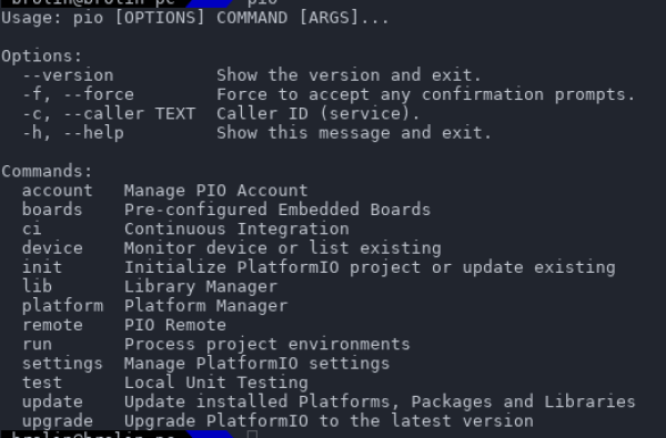
Entorno de desarrollo platformio
http://platformio.org/get-started
“PlatformIO is an open source ecosystem for IoT development Cross-platform IDE and unified debugger. Remote unit testing and firmware updates” http://platformio.org/
PlatformIO Core is a heart of whole PlatformIO ecosystem and consists of
- Multi-platform Build System
- Development platform and package managers
- Library Manager
- Library Dependency Finder (LDF)
- Serial Port Monitor
- Integration components (Cloud & Standalone IDE and Continuous Integration).
PlatformIO Core is written in Python 2.7 and works on Windows, macOS, Linux, FreeBSD and ARM-based credit-card sized computers (Raspberry Pi, BeagleBone, CubieBoard, Samsung ARTIK, etc.).
PlatformIO Core provides a rich and documented Command Line Interface (CLI). The other PlatformIO-based software and IDEs are based on PlatformIO Core CLI, such as PlatformIO IDE. In other words, they wrap PlatformIO Core with own GUI.
tomado de http://docs.platformio.org/en/latest/core.html
Project Configuration File platformio.ini http://docs.platformio.org/en/latest/projectconf.html
The Project configuration file is named platformio.ini. This is a INI-style file.
platformio.ini has sections (each denoted by a [header]) and key / value pairs within the sections. Lines beginning with ; are ignored and may be used to provide comments.
There are 2 system reserved sections:
- Base PlatformIO settings: Section [platformio]
- Build Environment settings: Section [env:NAME]
The other sections can be used by users, for example, for Dynamic variables. The sections and their allowable values are described below.
Dynamic variables: Dynamic variables/templates are useful when you have common configuration data between build environments. For examples, common build_flags or project dependencies lib_deps.
Section [platformio] env_default, home_dir, lib_dir, libdeps_dir, lib_extra_dirs, src_dir, envs_dir, data_dir, test_dir, boards_dir
Section [env:NAME] A section with env: prefix is used to define virtual environment with specific options that will be processed with platformio run command. You can define unlimited numbers of environments.
Ecosistema de librerías
Hundreds Popular Libraries are organized into single platform with advanced search by keywords, missed or known headers, etc.
elementos básicos del rompecabezas
- Sensores
- Actuadores Físicos o virtuales
- Tx/Rx de datos Inalámbrica o por cable
¿Para qué lo podemos usar?
Biostation

https://github.com/unloquer/TalleresESP/tree/master/bioStation
Luz / Cantidad de fotones
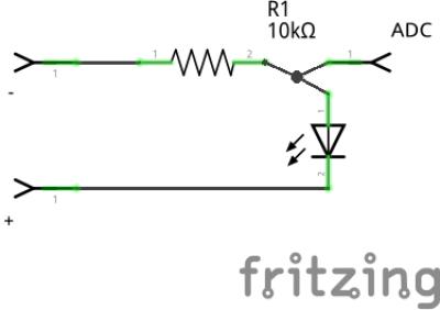
Hay varias maneras de medir luz, la mas comun y barata puede ser una fotoresistencia, que ademas es bastante conocida en el mundo del DIY. Un componente mas preciso y con mucho menos ruido es el fotodiodo; el fotodiodo es un semiconductor que transforma luz en corriente electrica, la luz que produce es debido a los fotones que almacena. Debido a que lo que necesitamos es leer esa corriente electrica, la alimentacion debe ser inversa, convertir un LED en un sensor de luz. Ya que el fotodiodo es bastante adecuado lo unico que necesitamos para tomar lecturas de el y medir la luz es conectarlo a traves de un divisor de voltaje al pin analogo del microcontrolador. Tener en cuenta que como necesitamos alimentarlo a la inversa el catodo -pata negativa del fotodiodo- va conectado a positivo del microcontrolador
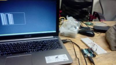
Este es un codigo que cada segundo saca una media de la cantidad de luz en donde se encuentra e imprime en la consola, mientras mas luz mas corriente y por lo tanto un valor mas alto. En nuestro garaje con la luz apagada da un muy bonito 0
#include "Arduino.h"

const int sensor_pin = 0;
int s_value, mean_value, sum_value;// variables para almacenar el valor, y la media de 20 muestras para un mejor resultado
int samples = 20;

void setup(){

  Serial.begin(9600);

}

void loop(){

  sum_value = 0;
  for(int i = 0; i < samples; i++){

// tomamos 20 muestras por segundo, 1 cada 50 ms

    s_value = analogRead(sensor_pin);

    sum_value += s_value;
    delay(50);

  }
// media de valores
  mean_value = sum_value/samples;


  Serial.print("mean value: ");
  Serial.println(mean_value);

}
https://makezine.com/projects/make-36-boards/how-to-use-leds-to-detect-light/
Soil Moisture
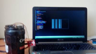
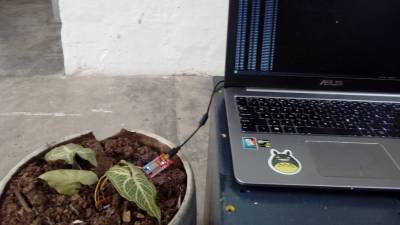
Para leer cambios de humedad en el suelo existen varias técnicas, una que nos interesó bastante es un circuito conductivo basado en el famoso timer 555, y el circuito es el mismo de un drawdio -mas emocionante todavia-; para los que en algún momento han construido ese lápiz que suena depronto se dieron cuenta que lo que hace el timer es apagarse y prenderse cada tanto tiempo, esto genera un pulso a cierta frecuencia y por eso suena :B .Un pulso puede tener diversos tiempos para sus tiempos de encendido y apagado o.O, digamos que tenemos un pulso que dura 1sg, podemos encender 0.5sg y apagar 0.5sg el timer, o que tal 0.1sg y 0.9sg? ^^, a esto se le llama “duty cycle”.La librería de arduino tiene una función que mide el tiempo que un input se encuentra en alguno de estos estados, se llama pulseIn(). En términos generales el duty cycle sube y la frecuencia baja mientras más húmedo se encuentre el suelo, aqui se abre la opción de generar más datos, todavía falta generar mas datos e implementar bien la relación duty cycle/frecuencia
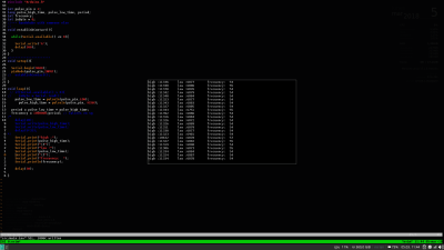
El código para leer la frecuencia a partir del periodo de tiempo formado por el pulso HIGH y LOW es el siguiente:
#include "Arduino.h"

int pulse_pin = 2;
// pulse in devuelve unsigned long, tener cuidado con el envio de esta variable a otros entornos

unsigned long pulse_high_time, pulse_low_time, period;
int frecuency;
int inByte = 0;

//---------------------
void setup(){

  Serial.begin(9600);
  pinMode(pulse_pin,INPUT);

}
//--------------------------------
void loop(){

    pulse_low_time = pulseIn(pulse_pin,LOW);
    pulse_high_time = pulseIn(pulse_pin, HIGH);

    period = pulse_low_time + pulse_high_time;

    frecuency = 1000000/period; // valores en sg, 10M de microsegundos son 1 segundo

    Serial.print("high :");
    Serial.print(pulse_high_time);
    Serial.print("\t");
    Serial.print("low :");
    Serial.print(pulse_low_time);
    Serial.print("\t");
    Serial.print("frecuency:  ");
    Serial.println(frecuency);

    delay(30);

}
probado en áreas pequeñas :3 y con bastante humedad
referentes:
https://en.wikipedia.org/wiki/Duty_cycle
https://www.arduino.cc/reference/en/language/functions/advanced-io/pulsein/
Automator

https://github.com/unloquer/TalleresESP/tree/master/autoMator
eMotion


